


 简体中文
简体中文 English
搜索结果建议
快速链接
Click to download the parameters setup tool for RTC8.
2025-07-22
2026-03-20


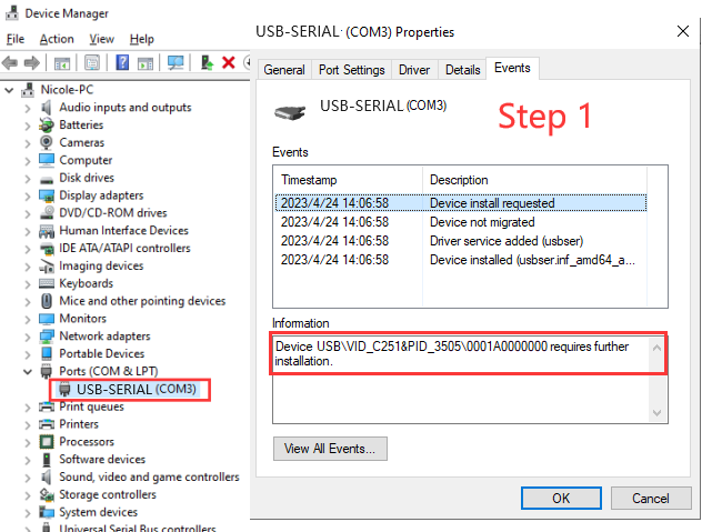
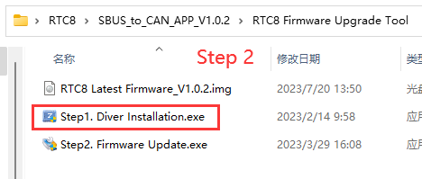
Step1. Driver Installation
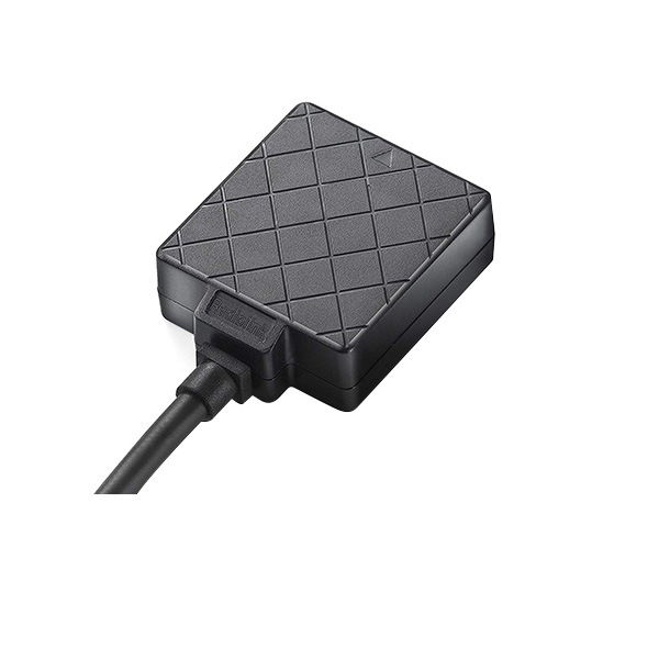
1. Use a USB cable to connect the RTC8 to the computer.
2. After the successful connection, there will be a new COM port in computer device manager.


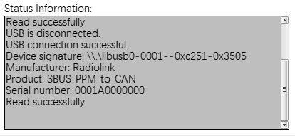
1. Status information display
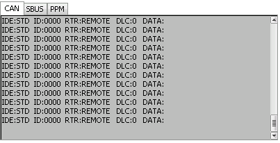
(1) CAN:
Display currently received CAN data (after filtering ID).
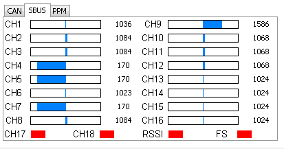
(2)SBUS:
If there is an SBUS signal input, the SBUS channel data will be displayed.
(3) PPM:
If there is a PPM signal input, the PPM channel data will be displayed.
3. Parameter configuration
Notice!
① Each time the device is connected, the parameters will be automatically obtained once and sent to the computer.
② All parameters must be written after modification. Click "Optimset" in the lower right corner, otherwise the parameters will not be set successfully.
(1) CAN Timing


① Preset baud rate selection: After selection, BS1, BS2, BRP, and SJW parameters will be automatically set. When the preset value does not meet the requirements, parameters of BS1, BS2, BRP, and SJW can be manually adjusted according to the actual situation.
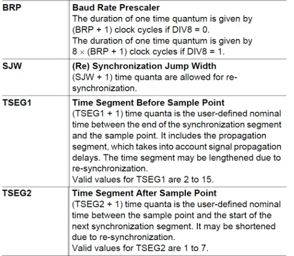
② BS1(TSEG1): Bit segment 1
③ BS2(TSEG1): Bit segment 2
④ BRP: The duration of one time quantum
⑤ SJW: (Re)synchronization jump width (The larger the value is set, the larger the baud rate error is allowed.)
Note:
① The synchronization segment is always 1.
② PTS and BS1 have been merged, so the width of BS1 is equal to the width of PTS+BS1.
③ Sample: Automatically calculate sampling points according to BS1 and BS2.
Configuration references:
https://blog.csdn.net/piaolingyekong/article/details/124276670
(2) CAN Acceptance Filter
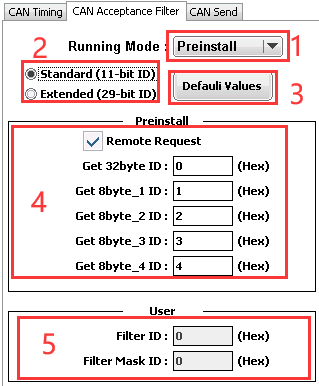
① Running Mode
(1) Preinstall: Only receive data matching the 5 IDs of the preset configuration.
A. Respond after receiving the Get 32byte ID, then send 32 data continuously.
(16 channels, 2 bytes per channel)
B. Respond after receiving Get 8byte_1 ID, and send 8 data.
(1-4 channels, 2 bytes per channel)
C. Respond after receiving Get 8byte_2 ID, and send 8 data.
(5-8 channels, 2 bytes per channel)
D. Respond after receiving the Get 8byte_3 ID, and send 8 data.
(9-12 channels, 2 bytes per channel)
E. Respond after receiving Get 8byte_4 ID, and send 8 data.
(13-16 channels, 2 bytes per channel)
(2) User: Receive data according to the configuration of (match ID) and (mask ID). Only reply. No additional data is sent.
(3) Silent: The working mode ID data can be received before selecting the Silent mode, but it
will not send a response signal.
Note: Only remote frame data is received in this mode.
② ID Mode:
A. Standard(Standard ID) , with ID range of 0-7FF
B. Extended(Extended ID), with ID range of 0-1FFFFFFF
Note: It is prohibited that all 7 bits are recessive. (Prohibited setting: ID=1111111XXXX)
③ Default Values
Click and all parameters on this page will be restored.
④ Preset ID
The ID that receives the channel data (Refer to Preinstall).
⑤ User Filter ID setting
If you only want to receive the standard frame whose CAN ID is 0x317, the setting method is as follows:
Filter ID: Set to the binary bit 011 0001 0111, corresponding to 317.
Filter Mask ID: Set to the binary bit 111 1111 1111, corresponding to 1FFFFFFF
If you want to receive standard frames whose CAN ID is 0x310 to 0x317, the setting method is as follows:
The meaning of each bit in Filter Mask ID:
(1) Bit x is set to 1, and the bit x of the received ID must be consistent with the bit x of the Filter ID, otherwise, it will be ignored.
(2) Bit x is set to 0, regardless of whether the bit x of the received ID matches or not, as long as all the bits of 1 game, the data will be received and responded to. Assuming the Filter Mask ID is set to 0, all messages will be received and answered to.
(3) CAN Send
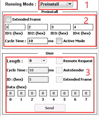
(1) Running Mode: (Consistent with CAN Acceptance Filter)
(2) Preset mode parameters:
① With Extended Frame not ticked, the ID range can be set from 0 to 7FF
② With Extended Frame ticked the ID range can be set from 0 to 1FFFFFFF
Note: It is prohibited that all 7 bits are recessive. (Prohibited setting: ID=1111111XXXX)
③ ID1: ID that sends data of channels 1-4
④ ID2: ID that sends data of channels 5-8
⑤ ID3: ID that is sending data of channels 9-12
⑥ ID4: ID that is sending data of channels 13-16
⑦ Cycle Time: The cycle of actively sending channel data
⑧ Active Mode: Active sending mode. When Active Mode is ticked, there is no need to send the command to obtain data to the SBUS/PPM to the CAN Protocol encoder, and the device will periodically send channel data to the CAN bus at the time set by Cycle Time.
(3) User Mode Parameters
① Length: User-defined data sending length
② Remote Request
③ Cycle Time: The cycle of automatically sending channel data
④ AutoSender: Automatic sending mode. When AutoSender is ticked, the device will periodically send the set user data to the CAN bus at the time set by Cycle Time.
⑤ ID: ID of sent data
⑥ With Extended Frame not ticked, the ID range can be set from 0 to 7FF
⑦ With Extended Frame ticked, the ID range can be set from 0 to 1FFFFFFF
Note: It is prohibited that all 7 bits are recessive. (Prohibited setting: ID=1111111XXXX)
⑧ Data: The data to be sent
⑨ Send: Send data key. Data is sent every time it is clicked.
* The Driver needs to be installed only when using the upgrade tool or parameter setup APP for the first time.

2. Debug/Status information
Parameters Setup Tool for RTC8(Please set by the Windows computer)


 简体中文
简体中文- English